|
FEA Geometry Element Types
Elements fall into four major categories: 2D line elements, 2D planar
elements, and 3D solid elements which are all used to define geometry; and
special elements used to apply boundary conditions. For example special elements
might include gap elements to specify a gap between two pieces of geometry.
Spring elements are used to apply a specific spring constant at a specified node
or set of nodes. Rigid elements are used to define a rigid connection to or within a
model. The figures below show nodes in red and the element in translucent blue
except for the beam element which is bright blue.
The most common geometry elements are show below. Most FEA tools support
additional element types as well as somewhat different implementations of even
these common elements.
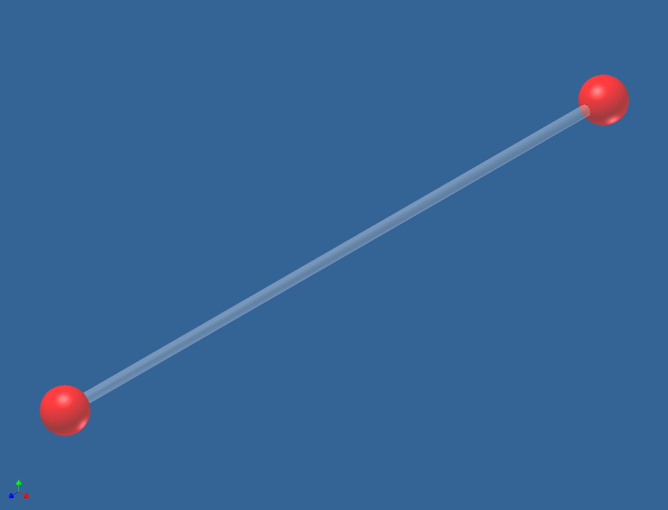 |
Truss Element (2D Line)
Truss elements are long and slender, have 2 nodes, and can be oriented
anywhere in 3D space. Truss elements transmit force axially only and are 3
DOF elements which allow translation only and not rotation. Trusses are
normally used to model towers, bridges, and buildings. A constant cross
section area is assumed and they are used for linear elastic structural
analysis. |
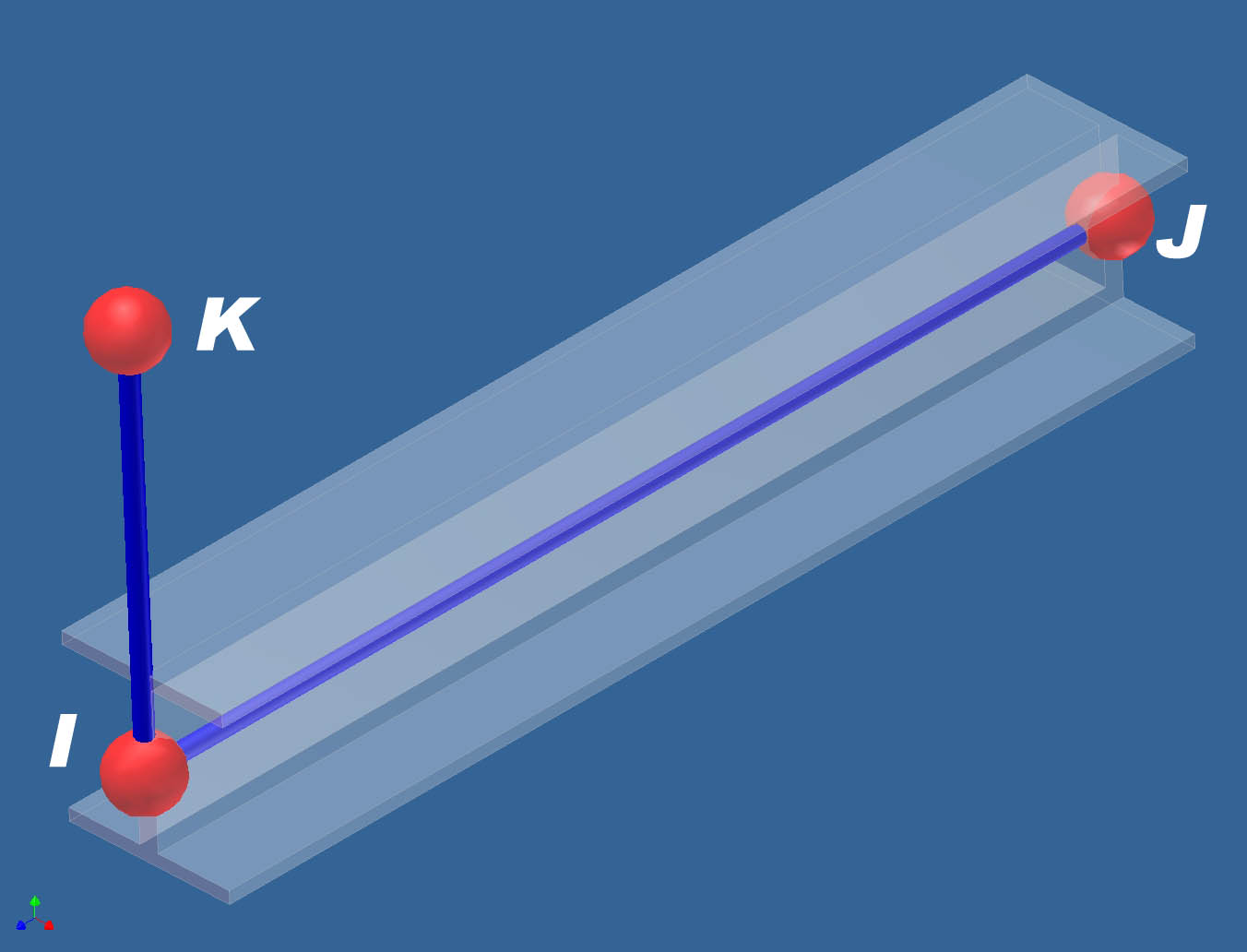 |
Beam Element (2D Line)
Beam elements are long and slender, have three nodes, and can be
oriented anywhere in 3D space. Beam elements are 6 DOF elements allowing
both translation and rotation at each end node. That is the primary
difference between beam and truss elements. The I J nodes define element
geometry, the K node defines the cross sectional orientation. This is how
you differentiate between the strong and weak axis of bending for a beam.
A constant cross section area is assumed. In the image, the beam shape is
shown only for visualization, the element is the dark blue rod. The I J
axis runs from the near to far node. K is shown vertically above the I
node or could be horizontally to the right of I. |
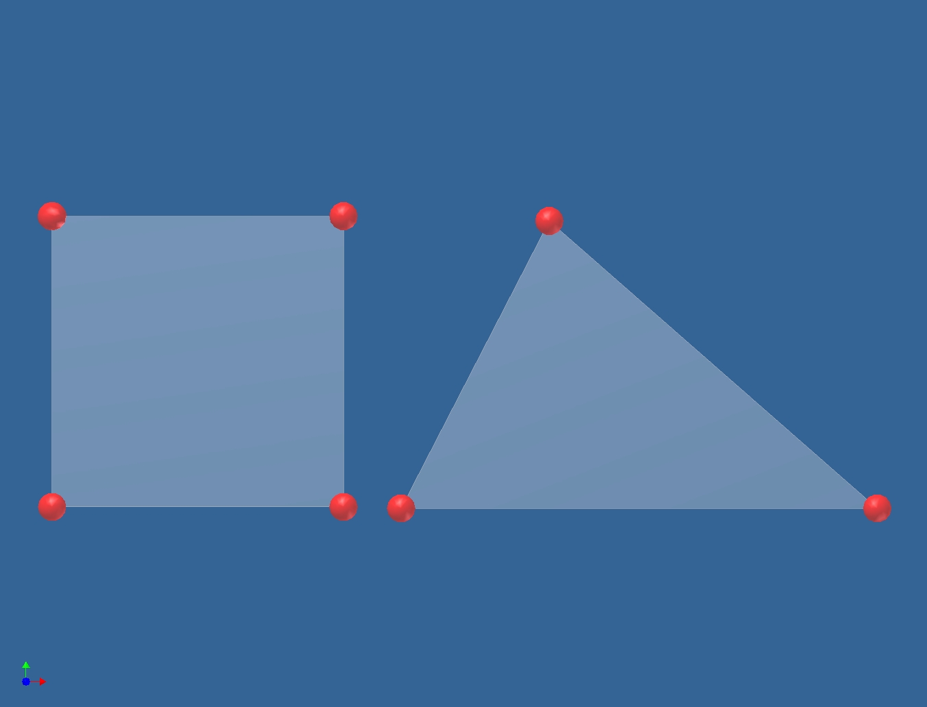 |
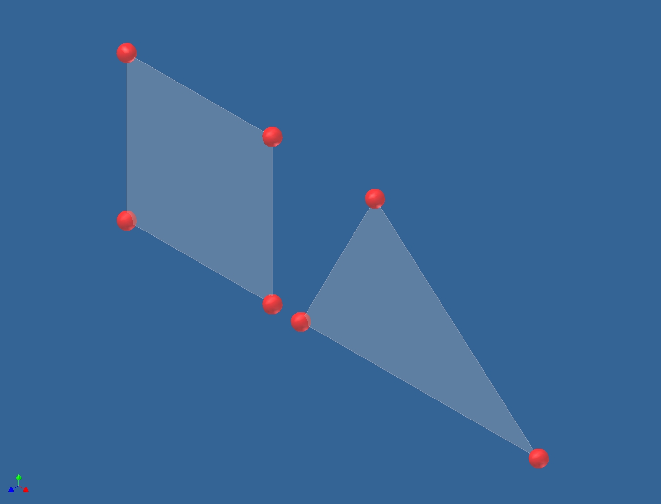
2D Element (2D Planar)
2D Elements are 3 or 4 node elements with only 2 DOF, Y
and Z translation, and are normally created in the YZ plane. They are used
for Plane Stress or Plane Strain analyses. Common applications include
axisymmetric bodies of revolution such as missile radomes, radial seals,
etc. and long sections with constant cross sectional area such as a dam.
Plane Stress implies no stress normal to the cross section defined -
strain is allowed - suitable to model the 2D cross section of a body of
revolution. Plane Strain implies no strain normal to the cross section
defined - stress is allowed - suitable to model the 2D cross section of a
long dam. |
 |
Membrane Element (2D Planar)
Membrane Elements are 3 or 4 node 2D elements that can be
oriented anywhere in 3D space. They can be used to model thin membrane
like materials like fabric, thin metal shells, etc. These elements will
not support or transmit a moment load or stress normal to the surface.
They support only translational DOF not rotational and in-plane loading.
The thickness of the membrane must be small relative to its length or
width. Membrane thickness is defined as a fixed parameter which can be
varied. The geometry is drawn at the midplane with zero thickness shown,
similar to a plate element. |
|
|
Plate / Shell Element (2D Planar)
Plate / Shell elements are 3 or 4 node 2D planar elements that can
be oriented anywhere in 3D space. They are typically used to model
structures comprised of shells such as pressure vessels, automobile
bodies, ship hulls, and aircraft fuselages. Generally a thicker wall than
for a membrane element but about 1/10 the length or width. All
translational DOF are supported as well as rotational DOF that are not out
of plane. That is rotation about the normal to the element surface is not
allowed. Plate thickness is defined as a fixed parameter which can be
varied. The geometry is drawn at the midplane with zero thickness shown.
Different FEA tools call these either Plates or Shells. This is the
preferred element type for most thin walled structures.
|
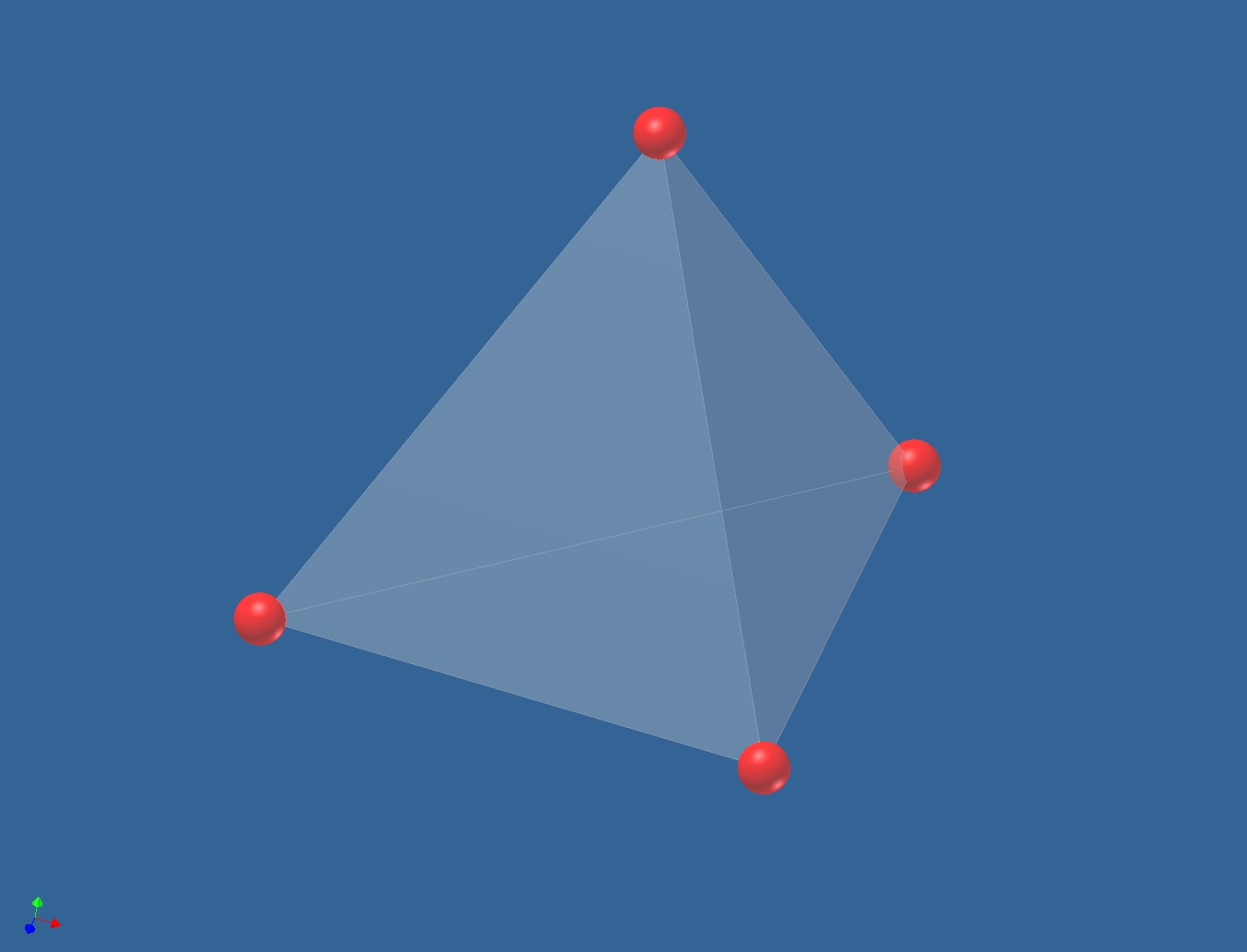 |
3D Tetrahedra Element, 4 Nodes (3D Solid)
See definition below for the 8 node brick, you can usually
specify either all tetrahedra, all bricks, or a mixture of both with some
automatic mesh generators. A mix of tets and bricks usually produces a
higher fidelity model. |
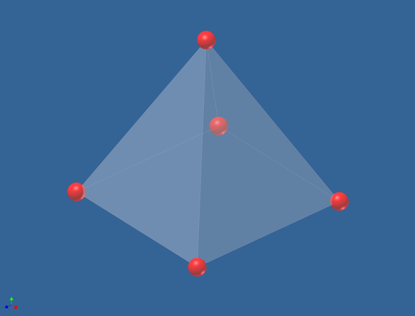 |
3D Tetrahedra Element, 5 Nodes, Pyramid (3D Solid)
See definition below for the 8 node brick, you can usually
specify either all tetrahedra, all bricks, or a mixture of both with some
automatic mesh generators. |
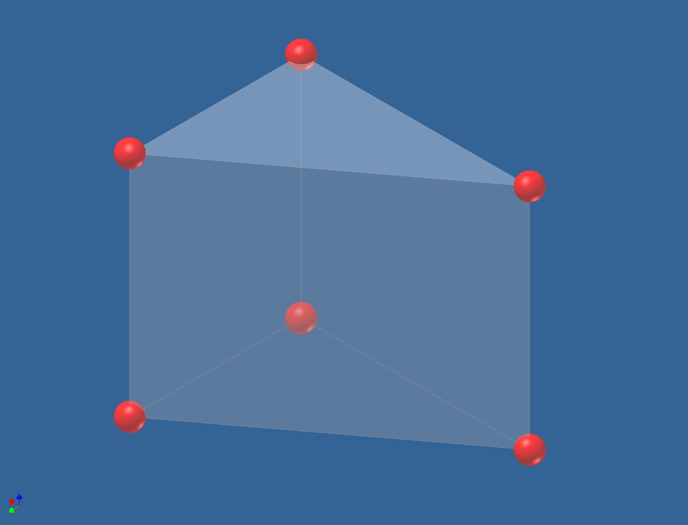 |
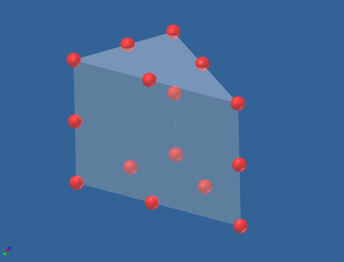
3D Tetrahedra Element, 6 Nodes, Wedge (3D Solid)
See definition below for the 8 node brick, you can usually
specify either all tetrahedra, all bricks, or a mixture of both with some
automatic mesh generators. |
 |
3D Tetrahedra Element with Midside Nodes, 15 Nodes,
Wedge (3D Solid)
See definition below for the 8 node brick, you can usually
specify either all tetrahedra, all bricks, or a mixture of both with most
automatic mesh generators. |
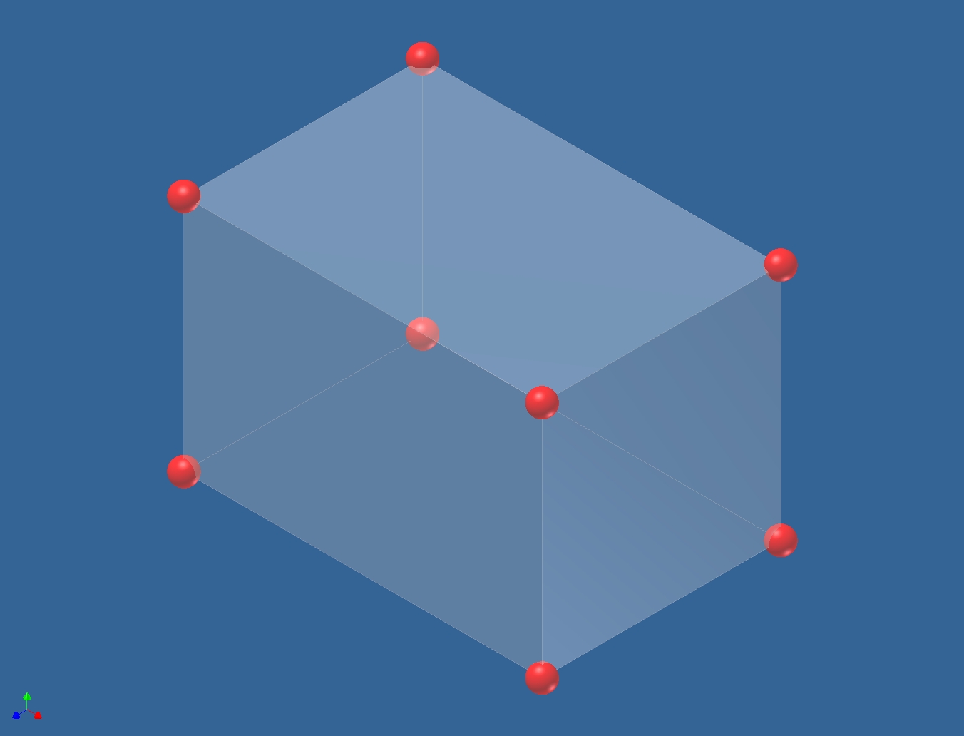 |
3D Brick Element, 8 Nodes (3D Solid)
Brick or tetrahedra elements may have 4, 5, 6, 7, 8, 15,
or 20 nodes and support
only translational DOF. They are normally used to model solid objects for
which plate elements are not appropriate. You can usually specify either
all tetrahedra, all bricks, or a mixture of both with some automatic mesh
generators. This is the most common, and frequently the only element type
supported by automatic mesh generators. Bricks work quite well for any
"blocky" structures which are typical of machined, cast, or forged
fabricated parts. Structural and thermal bricks exist so the same model
geometry can be used for both the initial steady state heat transfer and
subsequent thermal stress computations. Bricks compute stress through the
thickness of a part. |
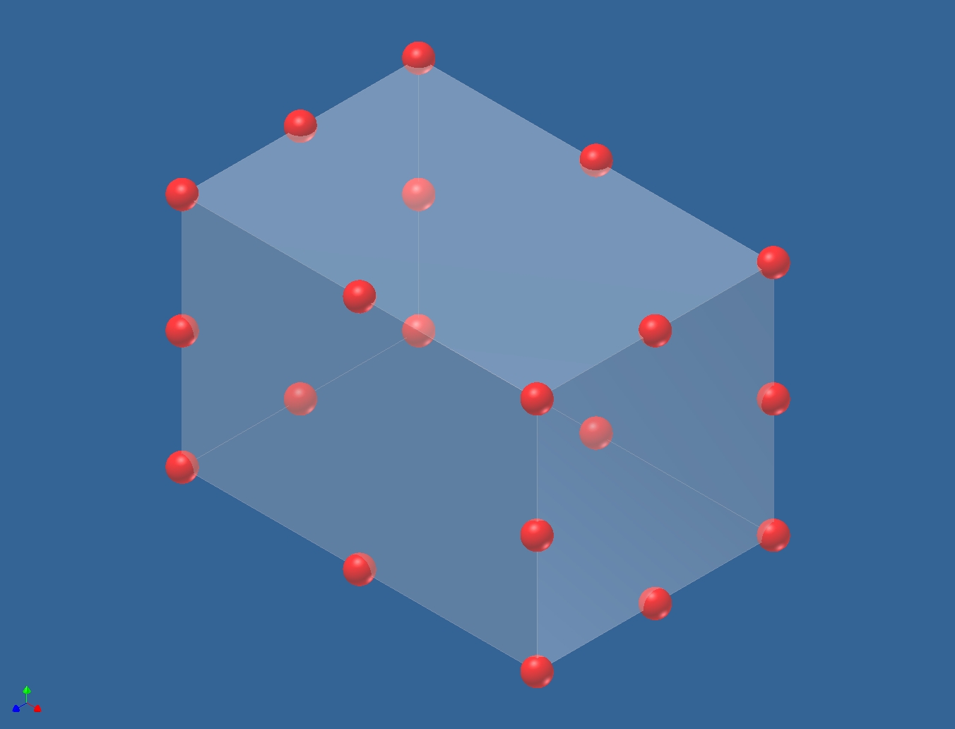 |
3D Brick Element with Midside Nodes, 20 Nodes (3D
Solid)
See definition above for the 8 node brick. Midside nodes
can be included if desired, also some FEA tools include an additional 21st
node at the centroid of the brick which can be useful in computation
quality comparisons. |
|